How to consider fluid dynamics in the design of elbow reducer castings
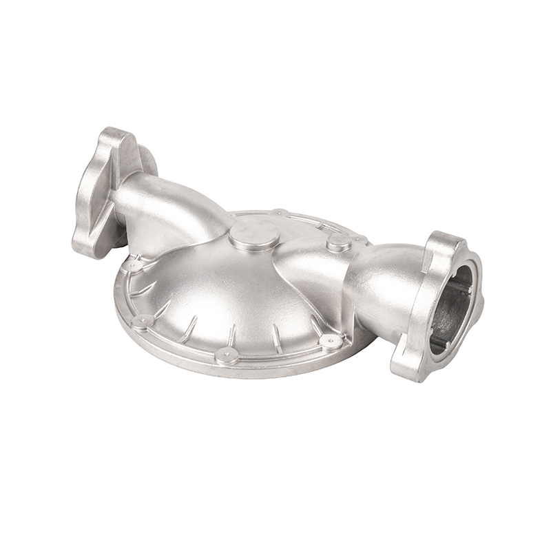
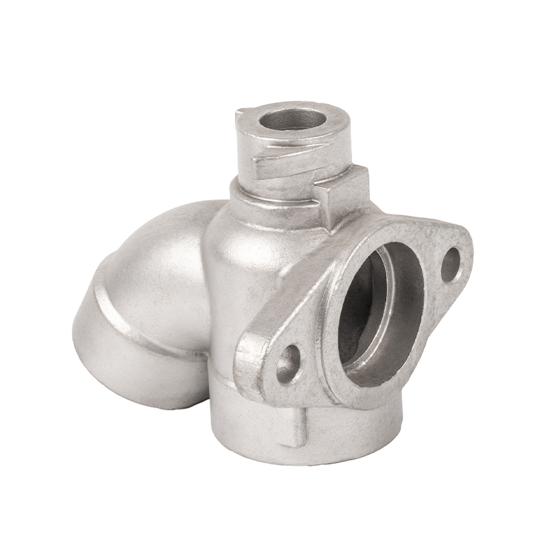
Elbow reducer castings, as key components for connecting and changing the direction of fluid in the pipeline system, directly affect the efficiency, safety and operating costs of the entire system. Professional design, especially at the level of fluid dynamics, is fundamental to ensuring its excellent performance. This is not just a simple size matching, but also a science about fluid behavior, energy conversion and structural optimization.
Minimize pressure loss and energy dissipation
In any fluid delivery system, the effective utilization of energy is crucial. One of the design goals of elbow reducer castings is to minimize pressure losses. Pressure loss is mainly composed of two parts: along-range loss and local loss. As a typical local resistance component, the design of an elbow reducer must be particularly concerned with how to reduce energy loss as fluid flows through.
Optimizing the design curvature is the top priority. When the fluid flows in a curved pipe, an inertial centrifugal force will be generated, resulting in uneven flow velocity distribution. An excessively small bending radius will aggravate the impact and separation of fluid from the pipe wall, forming a vortex, thereby dramatically increasing pressure loss. The ideal design should be a sufficiently large, smooth radius of curvature so that the fluid can turn smoothly and avoid sharp changes in flow direction.
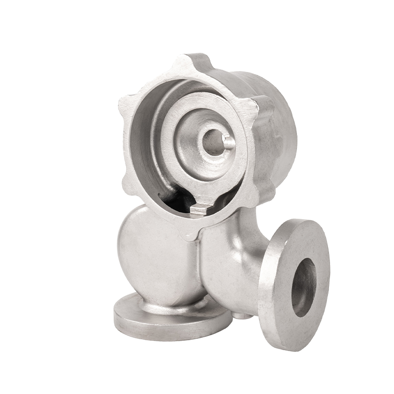
Smooth transition is another key principle. The design of the elbow reducer tube combines two functions: bending and variable diameter. During the transition from large diameter to small diameter, it is necessary to ensure a smooth transition of the inner wall to avoid sudden cross-sections. The sudden cross-section will form a stagnant and vortex zone, which not only increases local pressure loss, but may also cause cavitation and noise. By using a tapered or progressive shrinkage design, the fluid can be guided to accelerate smoothly, minimizing energy loss.
Suppress turbulence and eddy currents
Turbulence is an unstable state of fluid flowing at high speeds, which significantly increases frictional resistance and may cause vibration and noise. The design of elbow reducer should effectively suppress the generation of turbulence and eddy currents.
In the elbow part, unreasonable curvature or uneven inner walls can induce secondary flow and separation flow. The secondary flow is the circulating flow of fluid in the main flow direction on the cross-section, which will agitate the fluid and increase energy dissipation. The separation flow means that the fluid cannot fit tightly on the tube wall, forming a local reflux area. By optimizing the shape of the inner wall of the elbow, such as using an elliptical or non-circular cross-section, the flow velocity distribution can be controlled to a certain extent and the intensity of the secondary flow can be reduced.
In the variable diameter part, a reasonable cone angle is crucial. An excessively large cone angle will cause severe flowline separation in the contraction section, forming a reflux vortex. The reflux vortex not only consumes energy, but may also form local low-pressure zones on the pipe wall, causing cavitation and causing erosion and damage to the casting material. Therefore, the design must comprehensively consider the fluid type, flow rate and pressure, and choose an optimal cone angle to ensure smooth acceleration of the fluid and prevent flowline separation.
Prevent cavitation and material corrosion
Cavitation is a serious problem in fluid dynamics, especially in areas with high flow velocities and locally low pressures. When the fluid pressure is lower than its saturated steam pressure, steam bubbles will form. After these bubbles flow to the high-pressure zone with the fluid, they will collapse instantly, creating a powerful shock wave, causing mechanical erosion to the pipe wall.
In the design of elbow reducer castings, avoiding local low pressure zones is the key to preventing cavitation. This requires designers to ensure that the pressure distribution of the entire runner is stable, especially in the contraction and steering sections of fluid acceleration. By optimizing the geometry of the inner wall, eliminating areas that may cause abnormal increase in flow velocity or irregular flow lines, cavitation can be effectively prevented. In addition, it is also crucial to choose casting materials with good cavitation resistance, such as certain stainless steels or high chromium alloys.
Optimize fluid mixing and separation
In certain special applications, such as systems that require mixing two fluids or separating solid-liquid mixtures, the design of elbow reducer tubes requires consideration of the mixing or separation characteristics of the fluid.
For example, in the chemical industry, elbow reducer may be used to guide the two fluids for initial mixing. In this case, the designer can use secondary flow to enhance the mixing effect. By introducing a specific flow guide structure at the elbow or changing the shape of the inner wall, fluid turbulence can be increased and sufficient contact between the components can be promoted.
In mines or mud conveying systems, wear of elbow reducer tubes is a major problem. When solid particles move in the fluid, they will be thrown to the outer wall due to inertial centrifugal force, causing severe local wear. The design must be designed with a smooth large radius of curvature, and the wall thickness of the outer wall or the use of high wear-resistant materials to extend the service life of the components.
Consider fluid vibration and noise
When fluid flows in irregular flow channels, vibration and noise can occur. This not only affects system stability, but also may cause structural fatigue. The hydrodynamic design of elbow reducer castings must consider how vibration and noise are reduced.
A smooth inner wall surface is an effective way to reduce fluid friction and eddy current noise. After casting, fine machining or polishing can significantly improve the inner wall finish. In addition, optimizing the runner design to avoid streamline sudden changes can reduce impact noise caused by fluid impact and separation. Through tools such as finite element analysis, the structural vibration caused by fluid can be predicted at the design stage, and the structural rigidity of the castings can be adjusted accordingly or vibration-absorbing designs can be adopted.


 English
 Español
 русский
 中文简体
中文简体

