What should be paid attention to when designing the exhaust system during swirl impeller castings
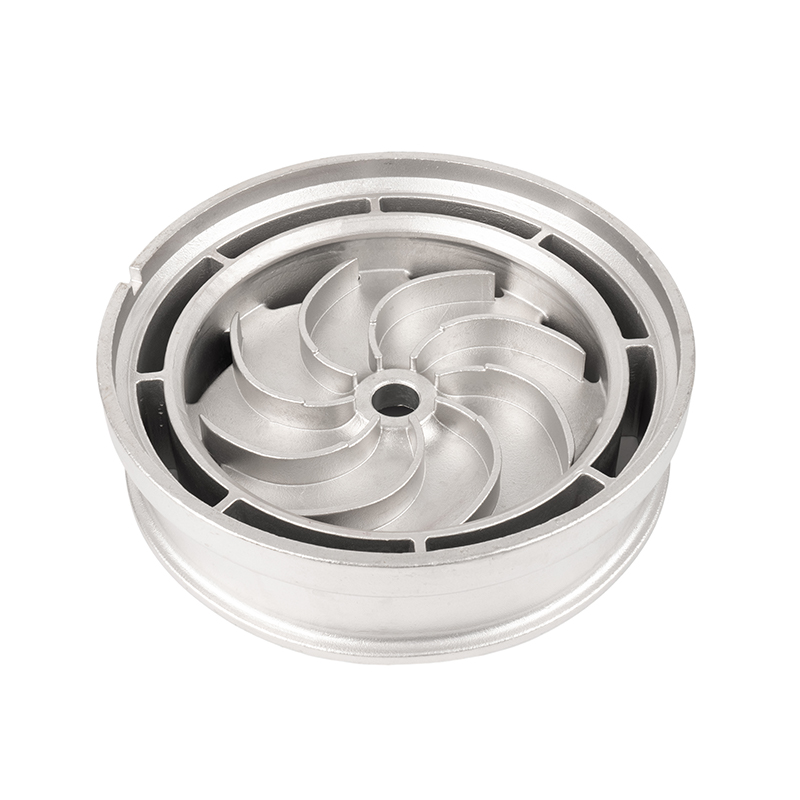
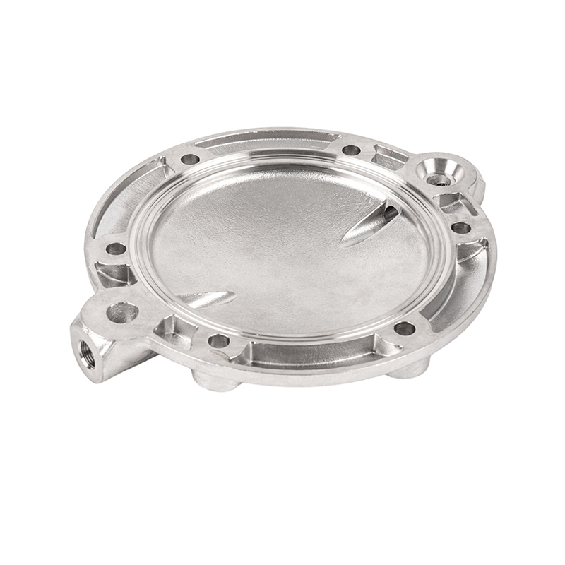
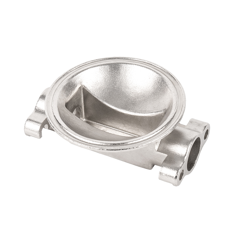
Swirl Impeller Castings are core components widely used in centrifugal pumps, turbine machinery and liquid mixing equipment. Due to its complex structure, high speed and strict performance requirements, gas emission control during the casting process is the key to ensure the compactness and performance reliability of the casting. The exhaust system design plays a vital role in the entire casting process, directly affecting the quality of metal liquid filling and the internal and external defect control of the final product. A scientific exhaust system can not only significantly reduce defects such as pores, cold shuts, flow marks, etc., but also improve process stability and casting yield.
Challenges of Swirl Impeller Structure to Exhaust Design
Swirl impellers usually have a multi-blade curved surface structure, with a thick center hub, thin and tortuous blades, and narrow internal channels. During the casting filling process, the molten metal needs to quickly fill multiple narrow paths. If the exhaust is not smooth, it is very easy to form back pressure, air stagnation, air entrainment and other problems.
The junction between the center hub and the blade root is often a typical "gas trapped area", and the gas is not easy to escape. The blades are close to the outer edge of the mold but relatively independent, and poor local exhaust will cause casting cold shut. If the gas cannot be discharged from the cavity between the blades in time, vortex formation will occur, increasing the risk of gas entrapment. Therefore, the exhaust system needs to be precisely designed to match the flow path and solidification sequence of the molten metal.
Reasonable arrangement of exhaust ducts and exhaust holes
The layout of the exhaust duct should give priority to the gas gathering position, the farthest end of the cavity and the last filling area. Usually, the exhaust structure needs to be set at the following positions:
Independent micro exhaust holes are arranged at the end or top of each blade;
Exhaust grooves and exhaust channels are set at the junction of the hub and the blade root;
All high-position areas at the end should be connected to the exhaust system at the top of the mold to form an unobstructed gas passage.
The diameter of the exhaust hole needs to be controlled between 0.2 and 1.0 mm, which is necessary to ensure smooth exhaust and prevent the molten metal from bubbling up to form flash. For sand casting, ceramic sand and coating with good air permeability can be used; during precision casting, exhaust cotton, ceramic fiber plugs, thin-walled exhaust pipes and other structures should be set on the outer layer of the shell mold to guide the gas to escape.
Air permeability and process control of mold materials
The air permeability of the mold directly affects the exhaust efficiency. When using resin sand or water glass sand, it is necessary to improve the air permeability by adding molding materials. For precision casting shells, the following measures can be taken to improve the shell exhaust performance:
Use hollow ceramic shells or lightweight aggregates to enhance overall air permeability;
Control the coating thickness and number of layers to avoid the shell surface being too dense;
Design a "breathable window" structure between the shell layers to connect the shell with the atmosphere.
After dewaxing, high-temperature sintering is performed to completely burn off the residual wax and moisture to ensure that there is no residual gas source in the shell cavity. If the shell is not fully sintered or dried, the enclosed gas will heat up and expand during the casting filling process, which may easily cause pores or shell explosion.
Control the filling speed and gas entrainment
The exhaust system needs to be highly matched with the filling process. Too fast filling will cause the molten metal to entrain a large amount of air, forming turbulence and eddy currents; too slow filling will easily cause local cold shuts, freezing of the metal front, and closed gas channels. Controlling the pouring speed and liquid flow direction can help the exhaust system to perform at its best.
When designing the gate system, the following should be done:
Avoid direct sprue pointing directly at complex structural areas to reduce impact and turbulence;
Set up a tapered inner gate to guide the molten metal to fill the mold in a laminar state;
Set up an auxiliary exhaust channel in the terminal area as a redundant path for gas release;
Appropriately reduce the pouring temperature and pressure head to slow down the tendency of gas entrainment.
When using vacuum casting or negative pressure assisted filling process, negative pressure can also be used to force the gas in the mold cavity to be discharged, improve exhaust efficiency, and significantly reduce the porosity of the casting.


 English
 Español
 русский
 中文简体
中文简体

