

 English
 Español
 русский
 中文简体


Home / News / Industry News / Working Principle of a Centrifugal Pump: Impeller, Casing and Flow Explained
Industry News
Working Principle of a Centrifugal Pump: Impeller, Casing and Flow Explained
Centrifugal pumps move more liquid than any other machine on a typical plant site, yet the principle behind them fits into a single sentence: spin a liquid, and the spin becomes pressure. That sentence is true, but it hides the parts that matter when a pump runs hot, noisy or short of flow. What follows is the longer version, explained the way we usually talk about it when a pump builder sends us a drawing and asks whether a certain geometry will behave.
What the Working Principle Really Means
A centrifugal pump is an energy converter, not a displacer. An electric motor turns the shaft, the shaft turns the impeller, and the impeller passes mechanical energy to the liquid in the form of velocity. Nothing inside the pump traps a fixed volume and squeezes it forward the way a piston does.
The second half of the conversion happens in the casing. Liquid leaves the impeller at high speed, and the casing slows it down in a controlled way. Whenever a moving fluid is decelerated, part of its velocity head becomes pressure head. That is why the discharge flange can read several bar while the suction side sits close to atmospheric.
There is a practical consequence worth remembering. Because the pump adds energy rather than a fixed volume, the flow it delivers is decided jointly by the pump curve and the system curve. Throttle the discharge valve and the pump simply moves to a different point on its curve, with less flow and, usually, less power draw. Close the valve completely and a centrifugal pump will still spin, quietly churning its own contents.
Following the Liquid Through the Pump
It helps to trace one litre of liquid from flange to flange. The sequence is always the same:
- Entry at the eye. Liquid flows into the suction nozzle and turns into the centre of the impeller. A well-shaped suction passage keeps that turn gentle, because every unnecessary bend costs suction performance.
- Pick-up by the blades. The rotating vanes sweep the liquid up and begin to spin it. Pressure at the impeller eye is the lowest point in the whole machine, which is exactly why cavitation starts there.
- Radial acceleration. As the liquid travels outward between the blades, the radius grows and the tangential speed grows with it. Kinetic energy rises sharply near the outer edge.
- Collection and diffusion. The liquid leaves the impeller and enters the volute or the diffuser passages. The cross-section expands, velocity falls, pressure rises.
- Discharge. The flow gathers at the outlet nozzle and leaves the pump at the pressure the system downstream demands.
One condition makes all of this possible: the impeller must be surrounded by liquid. A casing full of air has almost no mass to accelerate, so the pump spins without building head. That single fact explains why priming procedures exist and why a pump that loses suction mid-shift rarely recovers on its own.
The Impeller: Where the Energy Is Added
If the working principle has a heart, this is it. Blade angle, blade count, eye diameter and exit width together decide how much head a given diameter can produce and how much flow it can pass. Backward-curved blades give a stable, self-limiting curve that most water applications prefer. Radial and forward-curved designs appear where higher head or a different flow profile is needed.
Mechanically, impellers fall into three families. A closed impeller has shrouds on both sides and handles clean liquids with the best efficiency. A semi-open impeller exposes one side of the vanes, and an open impeller exposes both, which suits slurries and liquids carrying solids but costs some efficiency and demands careful clearance setting.
Because the flow passages are formed once, at the foundry, the internal finish of an impeller is a hydraulic feature, not a cosmetic one. Rough or mismatched passages, or a core that shifted slightly during pouring, show up later as a pump that misses its curve.
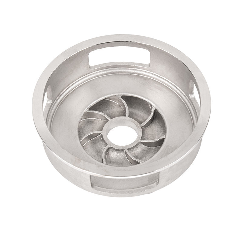 Stainless Steel Spiral Centrifugal Impeller CastingsInvestment-cast spiral impeller with controlled blade geometry and smooth passages, suited to centrifugal pumps where hydraulic finish and stable high-speed operation matter.View Product →
The Casing: Turning Velocity into Pressure
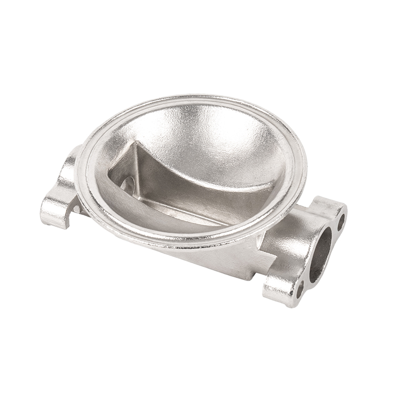
Most centrifugal pumps use a volute: a spiral chamber whose area increases steadily towards the discharge nozzle. The growing area is what slows the liquid down. Diffuser-style pumps achieve the same result with a ring of stationary vanes around the impeller, trading a little simplicity for better control of the velocity profile.
Clearances deserve attention here. Wear rings separate the high-pressure discharge region from the low-pressure suction region. As the gap between the impeller and the casing ring widens through erosion or abrasion, more liquid circulates back inside the pump instead of leaving through the nozzle. The result is a slow, quiet loss of performance that is easy to blame on the motor and hard to spot without a strip-down. Casting quality around those ring seats, flat and round within tolerance, is what keeps the gap stable over a long service life.
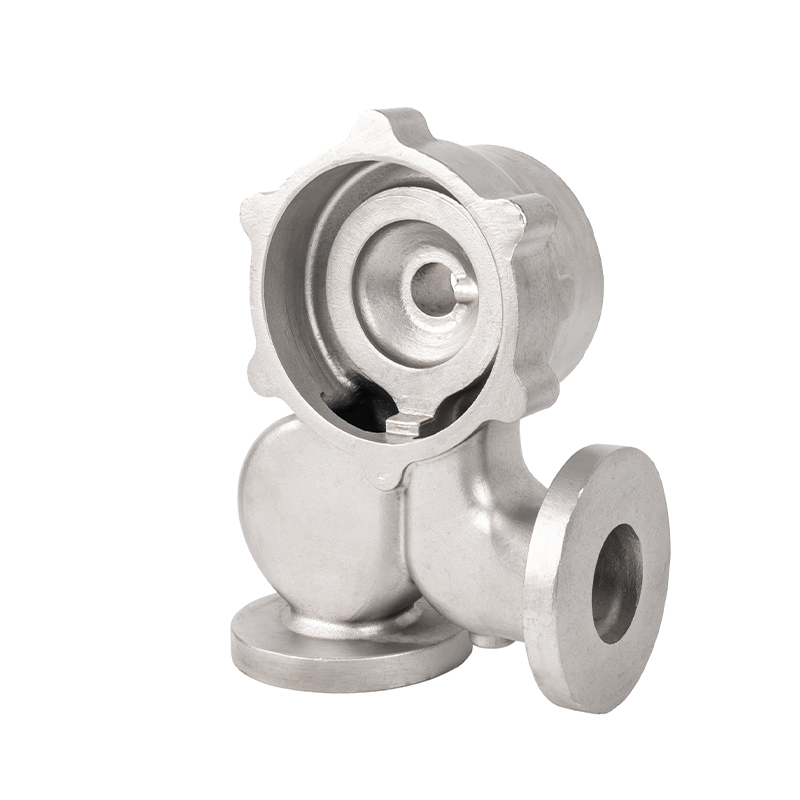 Custom Stainless Steel Centrifugal Pump CastingsOEM stainless pump castings for casings, impellers, shafts and bearings, with stable ring seats and smooth passages for efficient fluid transport.View Product →
The Numbers That Describe the Principle
Hydraulic language is compact, and a handful of terms carry most of the meaning. The table below is the short version we keep coming back to in conversation.
| Term | Plain meaning | Why it matters in practice |
|---|---|---|
| Flow rate (Q) | Volume moved per unit of time | Read directly from the duty point on the pump curve |
| Head (H) | Height the pump could lift the liquid to | Independent of liquid density, unlike pressure |
| NPSH | Margin above the liquid's vapour pressure | Too little of it means cavitation at the impeller eye |
| Specific speed | Impeller shape index at best efficiency | Guides the choice between radial, mixed and axial forms |
| Efficiency | Hydraulic power delivered versus shaft power in | Falls quickly when internal clearances open up |
Priming, Cavitation and the Limits of Suction
Suction is where the working principle meets thermodynamics. Every liquid has a vapour pressure, and that pressure rises with temperature. At the impeller eye, the local pressure is the lowest in the system. If it drops below the vapour pressure, pockets of vapour form and then collapse just downstream, producing the characteristic rattle of cavitation and, over time, pitted impeller surfaces.
Designers therefore compare the suction energy available in the installation with the energy the pump needs. Practical fixes are rarely exotic: raise the supply tank, shorten and widen the suction line, remove that unnecessary elbow before the flange, or cool the liquid a few degrees. All of them raise the pressure at the eye, which is the only thing the pump actually cares about.
Why the Casting Matters More Than People Expect
Hydraulic passages are born in a mould. The volute profile, the diffuser walls, the impeller channels and the sealing faces are all set by pattern and core geometry, and later machining only touches the surfaces that need a gasket or a bearing fit. A casting with heavy porosity near a sealing surface will leak no matter how carefully the pump is assembled. A casing whose wall thickness wanders will ring and vibrate under load.
That is the part of the work we know best. We have been supplying cast pump bodies, covers and impeller blanks to pump assemblers for years, and most of the technical conversation happens long before pouring, at the drawing stage, when wall thickness, draft angles and core support can still be adjusted cheaply.
Precision cast pump bodies and impeller blanks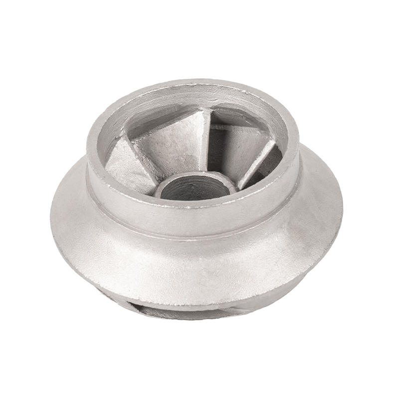 Precision Stainless Steel Blade Impeller CastingsPrecision-cast blade impellers in corrosion-resistant alloys, designed for centrifugal pumps, turbines and fans where blade geometry and surface finish affect efficiency.View Product →
When the Principle Is Working Against You
Once the mechanism is clear, symptoms become readable. A pump that delivers full pressure at shut-off but almost nothing at the nozzle usually has a problem on the suction side or a worn wear ring. A pump that shakes and growls when the flow is throttled back is often running too far left on its curve, with internal recirculation in the impeller. Rising vibration across a season, with no change in duty, points towards clearance growth, imbalance or a loosening fit. We wrote a longer field note on this in pump vibration causes and prevention for anyone chasing that particular thread.
Questions Pump Builders Ask Us
Does a centrifugal pump generate pressure by itself?
Not in the way a positive displacement pump does. It generates velocity, and pressure appears when the system resists the flow. On a completely open discharge, a centrifugal pump will still move liquid but will show very little pressure at the gauge.
Can it run dry?
Briefly, but nothing good comes of it. Without liquid there is no useful work and very little cooling, so seals and close-clearance surfaces suffer quickly. Suction protection is cheaper than a rebuild.
Why does the same pump deliver less after a few years?
Internal leakage is the usual answer. Impeller and casing ring clearances widen, more flow recirculates inside the pump, and the curve sags. Restoring the clearances often recovers most of the original duty without touching the motor.
The working principle of a centrifugal pump is short enough to write on a napkin, and deep enough to explain years of maintenance history. Spin the liquid, guide it outward, slow it down, and let pressure do the rest. Everything else, from blade angle to the flatness of a wear ring seat, is detail in service of that one idea.
RELATED PRODUCTS
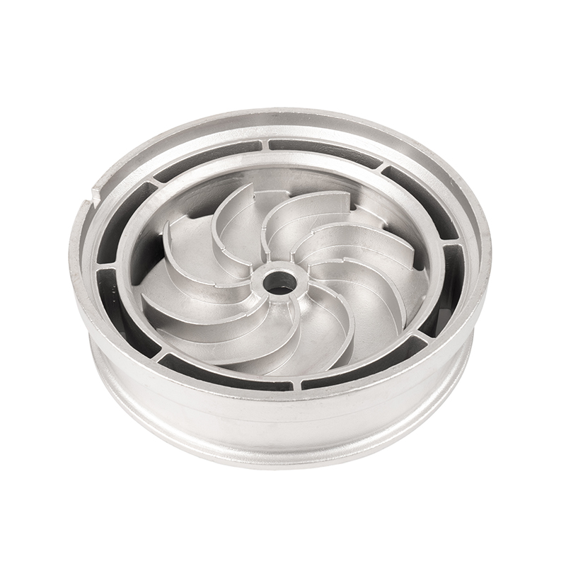
Do you have questions? Do not wait, Let's talk!
Contact Us
- Tel: +86-13967888380 / +86-13685858588
- +86-0574-86183698 / +86-0574-86183685
- Fax: +86-0574-86183696
- Email: [email protected]
[email protected] - Add: No. 68, Jiangbin Branch Road, Beilun Xiaogang Joint Development Zone, Ningbo, Zhejiang, China.
QR Code
Copyright © Ningbo Etdz Andrew Precision Cast Co., Ltd. All rights reserved
 Custom Metal Precision Casting Parts Manufacturers
